ESP-LXD Series
50-200 Station Two-Wire Decoder Commercial Controller
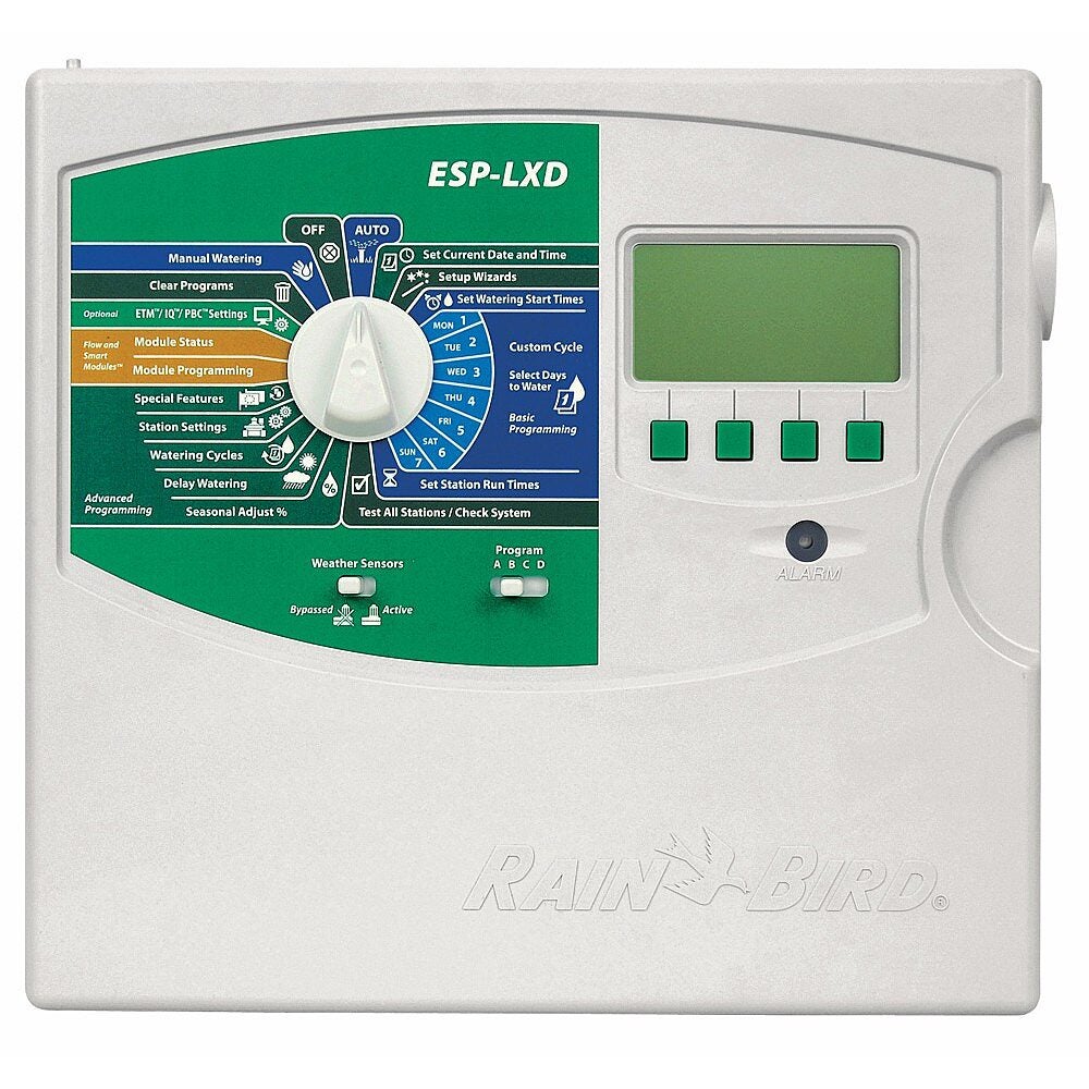
The ESP-LXD controller has been designed to maintain the look, feel and ease of programming of the ESP-LXME controller but with an interface to a two-wire path for decoder-based irrigation. The ESP-LXD controller can manage up to 50 stations but can easily be expanded for use with up to 200 stations. Flow Management is also built into every ESP-LXD controller.
Controller Features
- 50-station capability standard expandable to 200 stations with optional ESPLXD-SM75 modules
- Four available sensor inputs (one wired plus up to three decoder managed) with override switch
- Five flow sensors supported
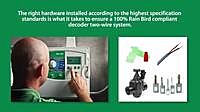
- Supported decoders: FD-101TURF, FD-102TURF, FD-202TURF, FD-401TURF, FD-601TURF
- Supports SD-210TURF sensor decoders (flow sensing and weather sensor support) and LSP-1 line surge protectors (one per 500 feet of two-wire path required)
- Central Control capable with Rain Bird IQ Communications Cartridges and software (see pg. 102)
- Advanced Features From Cycle+Soak™ to Contractor Default Program™, the ESP-LXD offers innovative features proven to cut installation expenses, troubleshooting time and water use
- Program backup and barcode decoder address entry with the optional PBCLXD
- Six user-selectable languages
- Removable front panel is programmable under battery power
- Plastic, locking, UV resistant, wall-mount case, Optional Metal and Stainless Steel Case & Pedestal
- Compatible with Rain Bird Landscape Irrigation and Maintenance Remote - Flow Smart Module™ factory installed or field upgradable
- Plastic, locking, UV resistant, wall-mount case, Optional Metal and Stainless Steel Case & Pedestal
Water Management Features
- Cycle+Soak™ by station
- Rain Delay
- Calendar Day Off
- Programmable Delay Between Stations by program
- Master Valve programmable by station
- Sensor programmable by station
- Program & Monthly Seasonal Adjust
Diagnostic Features
- Programming prompts
- Alarm light with external case lens
- Electronic circuit breaker
- Program review
- Variable test program
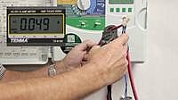
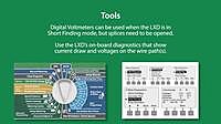
- Two-wire diagnostics to simplify and expedite troubleshooting
Operating Specifications
- Station timing: 0 min to 12 hrs
- Program level and global Monthly Seasonal Adjust; 0% to 300% (16 hrs maximum station run time)
- 4 independent programs (ABCD); ABC programs stack, ABCD overlap
- 8 start times per program
- Program Day Cycles include Custom days of the week, Odd, Odd no 31st, Even, and Cyclical dates
- Manual station, program, test program
Certifications
- UL, CE, CUL, C-Tick
Upgrade Options
- LXMM metal wall-mount case
- LXMM-PED metal pedestal
- IQ-NCC Network Communication Cartridge
- ESP-LXD-SM75 75-station module
- PBC-LXD Programming Backup Cartridge
Electrical Specifications
- Input required: 120 VAC ± 10%, 60Hz (International models: 230 VAC ± 10%, 50Hz; Australian Models: 240 VAC ± 10%, 50Hz)
- Power back-up: Lithium coin-cell battery maintains time and date while nonvolatile memory maintains the schedule
- Multi-valve station capacity: up to 2 solenoid valves per station; simultaneous operation of up to eight solenoids and/or master valves
Dimensions (W x H x D)
- 14.32” x 12.69” x 5.50” (36.4 x 32.2 x 14.0 cm)
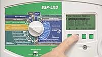
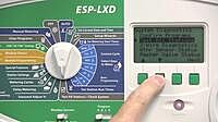
Why is the Alarm light on the controller front panel illuminated?
Turn dial to Auto and press Alarm button to view Alarm messages.
- Alarm message: Program will not auto run. Turn dial to Test All Stations / Check System. Select Program Summary to view missing programming information.
- Alarm message: Short Detect Mode. Turn dial to Test All Stations / Check System and select 2-Wire Diagnostics.
- Alarm message: No Decoder Module. Check module. Remove and reseat module.
- Alarm message: Flow Alarm. Turn dial to Flow Smart Module - Module Status and select View Flow Alarms to view flow alarms. Select Clear Flow Alarms to clear flow alarms.
- Alarm message: Duplicate Decoder Address. Turn dial to Setup Wizards, select decoder with duplicate address and change to the correct address.
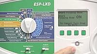
Why does the controller report that the 2-Wire Path is Off?
Turn dial to Off. Select 2-Wire Path button and press On.
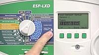
When I program station run times, why does the screen say “No Decoder Address”?
Turn dial to Setup Wizards and select Station Setup. Complete the setup wizard, entering a decoder address for each station.
One of my four 2-wire paths has been cut/damaged. How do I continue using the valves on my other 2-wire paths while I fix the cut/damaged 2-wire path?
Disconnect the damaged 2-wire path from the decoder module terminal strip and leave the other 2-wire paths connected.
The controller reports the Short Detect Mode is on due to a short on one of my 2-wire paths. How do I figure out which of my 2-wire paths has the short?
Disconnect all the 2-wire paths. The controller will exit the Short Finding Mode. Reconnect one 2-wire path at a time and monitor the controller display. When you add the 2-wire path that is shorted, the controller will automatically turn on the Short Finding Mode.
Why is the lower light on a decoder module(s) not illuminated?
The Decoder Module has detected a 2-wire path short and is in Short-Finding Mode. Turn dial to Test All Stations / Check System and select 2-Wire Diagnostics.
The controller reports that a weather sensor is preventing or pausing watering. How can I determine the status of my weather sensors?
Turn dial to Test All Stations / Check System. Select Weather Sensor Status to see the status of all Weather Sensors.
I need to repair a valve on my system but I have a Normally Open Master Valve. How do I turn of the Master Valve?
Turn dial to Off. MV Off follow directions to manually close the Normally Open Master Valve.
Why are valves operating on the wrong dates/times?
- Date/time is not set correctly. Turn dial to Set Current Date, Set Current Time and set current date/time.
- Unknown Start Days/Times have been entered. Turn dial to Test All Stations / Check System and select Program Review. Review the controller programming and remove any unwanted Start Days/Times.
- A Program Water Window has delayed watering. Turn dial to Test All Stations / Check System and select Program Review. Review Programs. Change Program Water Window to allow all full program run time.
Why can't the controller turn on the valve(s)?
- Controller may not be wired correctly to the decoder or the decoder to the valve. Turn dial to Test All Stations / Check System and select 2-Wire Diagnostics to test decoders, valve wires and solenoid.
- 2-Wire Path may be damaged/disconnected. Turn dial to Test All Stations / Check System and select 2-Wire Diagnostics to test decoders.
- Decoder address may not be correct. Turn dial to Test All Stations / Check System and select 2-Wire Diagnostics to test decoders.